
Solar Panel Installation on Flat Roof: Practical Guide to Design, Mounting and Maintenance
- Solar Panels London

- Jul 29
- 5 min read
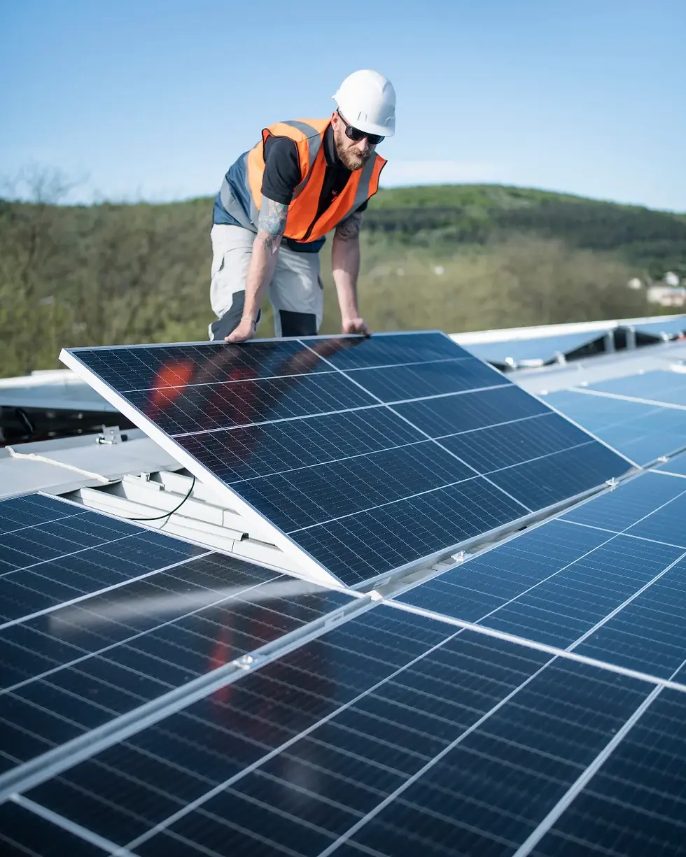
Installing a roof and solar installation on a flat roof gives you a flexible, accessible way to cut energy bills and boost property value. You can fit high-output photovoltaic panels on a flat roof using angled mounts or low-profile systems that maximise sun exposure while keeping wind risk and maintenance straightforward.
You’ll want to check roof condition, drainage, and load capacity before choosing ballast, framed racking, or penetrating mounts, because the right mounting strategy affects performance and warranty coverage. Professional survey and a clear plan for cabling, inverters and access will speed installation and reduce surprises. Solar Panels London recommends a thorough assessment before starting any roof and solar installation project.
Key Takeaways
Assess roof condition and load capacity before selecting a mounting approach.
Choose mounting and tilt options that balance output, wind resistance and warranty.
Plan for wiring, inverter placement and safe access to simplify installation and maintenance.
Essential Considerations for Flat Roof Solar Systems
You need to check structural capacity, roof condition, water drainage, and how panels will be angled and mounted. Pay attention to load limits, wind uplift, waterproofing details and shading that will affect performance and warranties.
Assessment of Roof Suitability
Before your roof and solar installation start with a professional roof survey that confirms age, membrane type, remaining life and any previous repairs. If your single-ply membrane is older than 15 years or shows multiple blistered areas, plan to replace it before mounting panels to avoid rework and warranty disputes.
Inspect for existing roof penetrations, HVAC units, skylights and rooftop access routes. Map out clear areas with at least 1m spacing for maintenance and inverter locations close to the electrical entry point to minimise DC cable runs.
Ask for structural drawings or have an engineer assess joist spacing, rafters and timber condition if the roof is timber decked. Flat roofs with timber or lightweight concrete decks often need reinforcement when adding ballast or framed racking.
Weight and Structural Loads
Calculate dead loads (panels, frames, ballast) and live loads (maintenance personnel, potential snow). Typical framed racking adds 10–20 kg/m²; ballast systems can add 40–80 kg/m² depending on design. Confirm your roof’s safe load per m² with an engineer before finalising the system type.
Consider point loads from penetrative mounts versus uniformly distributed ballast. Penetrative systems concentrate loads at fixings and need proper flashing and structural backing. Ballasted arrays distribute weight but can exceed roof limits if placed over small spans.
Include wind uplift and seismic factors in load calculations. Use local wind maps and a structural engineer’s input to determine anchorage, required ballast mass or mechanical fixings that satisfy building regulations and insurer requirements.
Orientation and Panel Tilt
On a flat roof you control azimuth and tilt; aim panels to face between 160° and 200° for best year-round production in the UK, with true south (180°) ideal when unobstructed. East–west bifacial or dual-row arrays can increase morning and evening yield if roof space limits optimal azimuth.
Set tilt between 10° and 30° depending on seasonality and wind loads; 15°–20° often balances production and reduced wind uplift. Higher tilt improves winter output and self-cleaning, but increases frame height and wind exposure.
Design row spacing to avoid inter-row shading at the sun’s lowest winter elevation. Use shading analysis or software to set minimum row separation; typically this requires 1.5–3 times the panel height depending on latitude and chosen tilt.

Weatherproofing and Drainage
Ensure mounting details maintain the integrity of the roofing membrane. For penetrative mounts, use manufacturer-approved flashed boots, solvent-welded collars or mechanically attached proprietary flashings to prevent leaks and maintain warranty compliance.
Plan drainage routes so ballast or mounted rails don’t pond water. Keep a 75–150mm clearance above the membrane in critical drainage paths and avoid blocking outlets or crickets. Where possible, align rows perpendicular to primary flow to assist runoff.
Specify corrosion-resistant materials (stainless steel, aluminium with suitable anodising or coatings) and UV-resistant seals at edges and penetrations. Include a maintenance access plan with regular checks for clogged outlets, membrane deterioration and seal integrity to protect both the roof and solar installation performance.
Installation Techniques and System Components
You will learn practical options for securing panels, choosing between ballast or mechanical attachment, and planning cable and inverter locations for performance and maintenance. Focus on structural load, roof membrane protection, and minimising DC run lengths to reduce losses.
Mounting Solutions for Flat Roofs
Choose between fixed-tilt frames, adjustable-tilt frames, and low-profile mounting rails. Fixed-tilt frames set panels at a single angle (commonly 10–20°) and are simplest to install; they reduce wind uplift when aligned with aerodynamic designs. Adjustable frames let you optimise generation seasonally or maximise yield if roof orientation is constrained.
Use corrosion-resistant aluminium or galvanised steel. Ensure the mounting system includes anti-slip pads and membrane-protective feet to prevent abrasion and ponding. For lightweight roofs, consider spreader plates or timber sleepers to distribute point loads and keep pressure within the roof’s load-bearing limits.
Ballasted Versus Attached Methods
Ballasted systems rely on weight (concrete blocks, pavers) to resist wind uplift and avoid roof penetrations. They suit roofs with high load capacity and intact membranes; typical ballast ranges from 30–120 kg per module row depending on wind zone and tilt. Verify ballast weight does not exceed your structural engineer’s allowance.
Mechanically attached systems use penetration anchors, through-bolts, or surface-mounted brackets tied into the building structure. They perform better in high-wind areas and allow lower ballast or none at all. Always use manufacturer-specified flashing kits and follow membrane-warranty procedures. Record penetration locations for future roof works and seal with compatible waterproofing materials.
For reliable roof and solar installation, Solar Panels London recommends consulting experienced professionals to ensure your project meets all safety and performance standards. Whether you choose a ballasted or mechanically attached system, proper planning and execution by Solar Panels London will help you achieve a long-lasting, efficient roof and solar installation.

Want to continue your solar research? Read our Roof Solar Panels Cost guide to understand installation expenses and potential savings, and explore In Roof Solar Panel Trays to learn how integrated mounting systems improve performance and aesthetics.
Wiring and Inverter Placement
For roof and solar installation projects, Solar Panels London recommends locating inverters as close to the array as practicable to minimise DC cable lengths and voltage drop. For string inverters, keep DC runs under 30–50 metres where possible; for microinverters, distribute them under each module to eliminate long DC runs entirely. Use UV-resistant, UV-stabilised conduit and cable trays to protect wiring from sun and mechanical damage.
Plan rooftop combiner boxes, DC isolators, and rapid shutdown devices near the array access point for safe maintenance during roof and solar installation. Solar Panels London advises placing inverters in shaded, ventilated enclosures with a clearance of at least 300 mm for airflow. Run AC cabling through separate conduits and ensure earthing is continuous with proper bonding to roof-mounted frames during every roof and solar installation.


Comments